top of page

Steering Column Redesign
01
Redesigned the steering subassembly for Berkeley Formula Racing's B23 FSAE car
The primary goals of redesigning the steering column from the ground up were to eliminate the compliance/play that existed in the previous design, improve the position and ergonomics of the design, as well as minimize the weight of the subassembly.
This was accomplished by simplifying the design from 2 Universal-Joints to a single Universal-Joint design. While this transition did introduce nonlinearities in the steering response, these were heavily analyzed and enough modifications were made such that the nonlinearities are negligible in the final design.
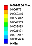
The part was also optimized through simulation in ANSYS through a series of load cases that model the worst case scenarios faced in the actual car.
The part experienced zero failures at competition and passed technical-inspection on the first try. B23 went on to achieve a 2nd place finish in the Autocross event out of 120+ teams.

B20 Column (old)
4.57lbs
~0.07in
Deformation at 60lbf pull

B23 Column (new)
2.27lbs
50% reduction
~0.01in
Deformation at 60lbf pull
A full exploded view of the top portion of the column can be seen to the right. The main shaft consists of two 4130 Steel tubes of different diameters (the bottom one has been optimized to a maximum possible torque while the top tube was lighter to package the following way) with a U-Joint in the middle.
There are then two needle roller bearings that go inside a "bearing cup/sleeve" which connects to the supports and the chassis of the car.
There is also a thrust bearing which is held to the shaft by a shaft collar, thus transferring the pull loads on the steering wheel into the supports.


Connection between the steering rack and lower tube is a splined input shaft + insert to weld it to the tube.
Connection between lower tube and U-Joint is done with an insert that interfaces using a cross bolt (+ pin if needed).


Connection between upper tube and U-Joint is a cross bolt (with saddle washers) + pin if needed.
Upper tube welds straight to the steering wheel quick release spline shaft.
Manufacturing and Jigging


Integrated in the car


Element mesh and section view for all sims performed
Pull Load Case
60lbf


Von Mises (ksi)
Deformation x140 (in)
Down Load Case
50lbf


Von Mises (ksi)


Deformation x48 (in)
Compound Load Case 60lbf + 30lbf


Von Mises (ksi)


Deformation x120 (in)
bottom of page